SURGE — rise time
CH1 left; CH4 right
Sets the rising-stage time. Rise CV is the adjacent input marked by a rising-slope glyph.
Leviathan for VCV Rack 2 · Open Source
A dual-slope generator, variable curvature slew limiter, precision attenuverter suite, and analog logic mix matrix.
Two independent outer function cores with sub-milli-Hertz to audio-rate speed, two central DC attenuverters, dedicated phase gates, and normalized OR / SUM / INV bus synthesis.
Core concept
Integral Flux is built on two primary outer channels (CH1 and CH4) and two precision utility channels (CH2 and CH3). Channels 1 and 4 can operate as free-running or triggered function generators, LFOs, audio-rate VCOs, or voltage slew limiters with continuously variable curvature from logarithmic through linear to exponential.
Signal routing
CH1/CH4 core → two parallel paths: direct UNITY output, and attenuverter → +/-10V clamp → variable OUT.
CH2/CH3 input (or +10V/+5V reference) → attenuverter → +/-10V clamp → variable OUT.
Each variable channel also feeds the internal bus while its OUT is unpatched: SUM = clamped sum; INV = −SUM; OR = maximum of zero and the four bus voltages. EOR/EOC gates follow core stage or slew direction independently.
Panel tour
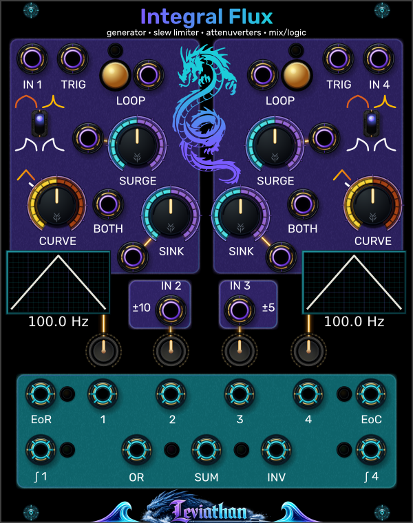
CH1 is on the left, CH4 on the right; CH2 and CH3 are the center utility channels. The two views below separate controls from jacks. Repeated numbers identify the same control or port type on different channels.
CH1 left; CH4 right
Sets the rising-stage time. Rise CV is the adjacent input marked by a rising-slope glyph.
CH1 inner left; CH4 inner right
Sets the falling-stage time. Fall CV is the jack below and toward the outside of each SINK knob.
Gold buttons near the top
Each button latches cycling on or off. The small light above it indicates cycling; the separate jack beside it is Cycle CV (10).
Large outer knobs
Shapes rise and fall. Mirror mode is linear at 33% travel; Shark Fin is linear at 50%. Shape also affects timing.
Small vertical switches above CURVE
Select Mirror or Shark Fin independently for CH1 and CH4. These switches are controls, not jacks.
Two windows below CURVE
Show nominal cycle geometry and a calculated frequency estimate. The animated phase dot is visible only for active functions at low rates.
Four small knobs in a row, CH1 → CH4
Control the four numbered outputs and their bus contributions. Center = zero, counter-clockwise = inverted, clockwise = positive. CH2/CH3 use +10V/+5V references when their inputs are unpatched.
Purple-ringed jacks are inputs; cyan-ringed jacks are outputs. Rise and fall CV use slope glyphs; Cycle CV sits beside LOOP. The unity outputs carry ∫ 1 and ∫ 4 labels. Click a numbered marker to reach its description.
Outermost top jacks
Feed the CH1/CH4 slew limiters when idle. During a triggered or cycling function, the input perturbs the function core.
Top jacks beside IN 1 / IN 4
Left TRIG drives CH1; right TRIG drives CH4. Rising edge at 1V, re-arm at 0V. Triggers during rise are ignored; accepted triggers during fall reset the core to 0V.
Jacks beside the gold LOOP buttons
A gate at or above 2.5V enables cycling. These are separate from TRIG. Cycling stays on if the LOOP button is latched, even with low Cycle CV.
Rising-slope glyphs beside SURGE
CH1 on the left; CH4 on the right. Positive CV lengthens rise; negative CV shortens it.
Jacks between CURVE and SINK
Affects rise and fall together. Positive CV speeds up; negative CV slows down. The saturating response is not calibrated 1V/oct.
Falling-slope glyphs below SINK
CH1 on the left; CH4 on the right. Positive CV lengthens fall; negative CV shortens it.
Center pair above the attenuverters
Feed the CH2/CH3 attenuverters. Unpatched: IN 2 supplies +10V and IN 3 supplies +5V. These channels do not slew.
Four middle jacks in the upper output row
Each output follows its matching attenuverter and clamps to +/-10V. Patching one removes that channel from SUM, INV, and OR.
Outer jacks in the upper output row
Left EoR belongs to CH1: high during fall. Right EoC belongs to CH4: high during rise. Both are low at idle; in slew mode they indicate downward/upward motion respectively.
Outer jacks in the bottom output row
Direct CH1/CH4 core outputs, bypassing attenuverters and their clamps. Patching these keeps the variable channels in the mix bus. The integral-symbol labels identify these unity outputs.
Three middle jacks in the bottom row, left to right
OR selects the highest positive bus voltage. SUM adds the unpatched variable channels and clamps to +/-10V. INV is the negative of SUM.
CV and patching
Integral Flux follows the classic Make Noise Maths normalization conventions with modernized high-speed CV response.
| Port | Type | Range / Voltage | Operational Behavior |
|---|---|---|---|
| IN 1 / IN 4 | Signal In | +/-10 V audio / CV | Input to the shaped slew limiter. When not cycling or running a triggered function, the output tracks this input with the rise and fall slew rates set by the dials. |
| TRIG 1 / TRIG 4 | Trigger In | Rising edge at 1 V; re-arm at 0 V | Starts a rise phase; triggers during rise are ignored. A trigger during fall resets the core to 0V before rising. A trigger from idle slew starts from the current core voltage. Accepted triggers have a 0.5 ms re-arm interval. |
| CYCLE 1 / CYCLE 4 | Gate In | High threshold 2.5 V | Engages cycling at 2.5V or above, in addition to the latched Cycle button. A low gate cannot override a latched-on button. Releasing the gate lets the current cycle finish. |
| RISE CV / FALL CV | Modulation | +/-10 V exponential | Exponential time scaling. Positive voltage increases time (slower); negative voltage decreases time (faster). |
| BOTH CV | Modulation | Bipolar, saturating speed control | Scales both stage times: positive CV speeds up, negative CV slows down. The response is saturating rather than calibrated 1V/oct. Rise/fall ratio is preserved until timing limits intervene. |
| IN 2 / IN 3 | Signal In | Normaled to DC | Unpatched normaling: IN 2 is normaled to +10V DC; IN 3 is normaled to +5V DC. Patching a jack overrides the internal DC reference. |
| 1 / 4 (Variable OUT) | Variable Out | +/-10 V (attenuverted) | Scaled by the respective CH1/CH4 attenuverter knob. Patching this jack disconnects the channel from the SUM, OR, and INV mix bus. |
| ∫ 1 / ∫ 4 (Unity) | Direct Out | Nominal 0 to 10.2 V function | Direct core output, bypassing the attenuverter and its +/-10V clamp. Slew output can be bipolar. Patching Unity does not remove the channel from the mix bus. |
| 2 / 3 (Variable OUT) | Variable Out | Unpatched: +/-10 V / +/-5 V | Attenuverted channel output, clamped to +/-10V with an external input. Unpatched input references are +10V on CH2 and +5V on CH3. Patching an output removes that channel from the mix bus. |
| EOR (CH1) | Gate Out | 0 V / +10 V | End of Rise: +10V during Fall, 0V during Rise and idle. In slew mode, high while moving downward. |
| EOC (CH4) | Gate Out | 0 V / +10 V | End of Cycle: +10V during Rise, 0V during Fall and idle. In slew mode, high while moving upward; this is not a short completion pulse. |
| SUM | Mix Bus | +/-10 V (clamped) | Algebraic sum of all unpatched variable channels: V1 + V2 + V3 + V4. LED reflects SUM polarity (green = positive, red = negative). |
| INV | Mix Bus | +/-10 V (clamped) | Inverted sum output: -SUM. Ideal for complementary ducking envelopes and cross-fade pan laws. |
| OR | Mix Bus | 0 to +10 V | Analog OR / Peak Selector: outputs max(0, V1, V2, V3, V4). Creates complex composite envelopes and waveshaped harmonics. |
Modes of operation
Each outer channel seamlessly morphs between transient envelope generator, periodic oscillator, and external signal slewer based on how you patch it.
When triggered via TRIG IN or when CYCLE is engaged:
When a cable is connected to SIGNAL IN, Cycle is disabled, and no triggered function is active:
Curvature engine
Unlike simple linear slew processors, Integral Flux features continuous curvature reshaping that retains natural transient punch and analog envelope feel.
| Curvature Position | Rise Characteristic | Fall Characteristic | Musical Application |
|---|---|---|---|
| Full CCW (Logarithmic) | Fast initial burst, slow rounding at crest | Slow initial drop, faster finish | Rounded attacks and falls that accelerate toward zero. |
| 33% (Linear in Mirror mode) | Constant slope rate (ramp up) | Constant slope rate (ramp down) | Clean pitch glissandi, symmetrical LFO triangles, precise modulation sweeps. |
| Full CW (Exponential) | Slow creeping start, explosive peak rise | Fast initial drop, gentler finish | Accelerating attacks and decays that slow toward zero. |
Visual inspection
Each outer channel is accompanied by a dedicated visualizer window rendered with sub-pixel vector precision.
The display previews one nominal cycle of the function corresponding to the current Rise, Fall, and Shape knob settings:
Below each waveform window, the calculated frequency estimate (1 / (rise time + fall time)) adapts its units. It is not a measurement of external input frequency:
120 Hz, 1.05 kHz).mHz) (1 mHz = 1000 seconds per cycle). The readout rounds to whole mHz, so very slow rates may display 0 mHz.Engine settings
Right-click the panel to configure anti-aliasing and performance optimizations tailored to your CPU and patch complexity.
| Setting | Default | Description |
|---|---|---|
| Bandlimited EOR/EOC | Disabled | Applies minBLEP anti-aliasing to the sharp edges of EOR and EOC gate transitions, reducing aliasing when using the gates as audio signals. |
| Bandlimited CH1/CH4 Signal Outputs | Enabled | Applies bandlimiting to sharp envelope reset edges when retriggering. Ideal when using Integral Flux as an audio oscillator. |
| Timing Update Rate | 1 (Per-sample) | Allows control-rate decimation (/4, /8, /16, /32) of timing parameter calculations under heavy CV modulation to reduce CPU load. Interpolate Timing Updates (enabled by default) smooths timing changes between updates. |
| Preview Tracer | Enabled | Toggles the low-rate animated phase tracer. Select Mirror or Shark Fin using each channel's panel switch. |
Patch recipes
Integral Flux excels at transforming simple modular signals into animated acoustic movement.
Goal: Tight, punchy envelope for VCA bass and drum plucks.
1. Patch gate/trigger sequencer into TRIG 1.
2. Set Rise to ~10% (snappy attack) and Fall to ~35% (medium decay).
3. Use Mirror mode and turn Shape clockwise from its 33% linear point for a decay that falls quickly then slows.
4. Connect UNITY 1 to your VCA CV input.
Goal: Divide an incoming master clock by /2, /3, or /4 without dedicated divider modules.
1. Turn CYCLE 1 off and patch master clock into TRIG 1.
2. Take output from EOR 1 into your sequencer clock input.
3. Keep Fall short and lengthen Rise across multiple input clock periods. Tune while monitoring EOR; ratios depend on timing.
Goal: Separate glide-up and glide-down slew rates for keyboard leads.
1. Patch 1V/Oct pitch CV into INPUT 1.
2. Ensure CYCLE 1 is OFF.
3. Set Rise to ~25% and Fall to 0%.
4. Patch UNITY 1 into your oscillator's V/Oct input.
Goal: Dual-operator audio FM voice without dedicated VCOs.
1. Enable CYCLE on both CH1 and CH4.
2. Turn Rise and Fall on both channels to near-minimum (frequency depends on Shape; watch the readout).
3. Patch OUT 1 into CH4 BOTH CV, and OUT 4 into CH1 FALL CV.
4. Listen to UNITY 1 or UNITY 4 through an audio output module. Patching OUT 1 and OUT 4 removes both from the internal mix bus.
Goal: Extract dynamic amplitude contours from external acoustic audio.
1. Rectify acoustic audio with an external rectifier, then patch the unipolar signal into INPUT 4. Turn CYCLE 4 off and leave TRIG 4 unpatched.
2. Set Rise to 0% (fastest available rise).
3. Set Fall to ~30% (smooth decay between syllables or hits).
4. Patch UNITY 4 into a filter cutoff or VCA CV input.
Goal: Rectify a sine wave and set a positive voltage floor.
1. Patch an audio sine wave into INPUT 2.
2. Set CH2 gain to +75% (about 87.5% knob travel). Center CH1 and CH4 attenuverters and leave OUT 2/OUT 3 unpatched.
3. Monitor the OR output jack.
4. Adjust CH3 attenuverter knob (DC offset) to inject bias into the OR bus.
max(0, V1, V2, V3, V4). A positive CH3 reference raises the output floor; it does not add an offset to CH2. This is rectification and peak selection, not wavefolding.Troubleshooting
Check if a cable is plugged into that channel's variable OUT jack (e.g., OUT 1, OUT 2, etc.). Patching a dedicated channel variable output jack removes that channel from the SUM, OR, and INV mix bus. For CH1/CH4, use UNITY to tap the core without removing the variable channel from the bus. CH2/CH3 have no separate unity outputs.
Integral Flux uses this trigger rule: an incoming trigger pulse received during the Rise phase is ignored to protect the integrity of the attack transient. Incoming triggers will immediately restart from 0V during Fall; from idle slew, the rise begins at the current core voltage.
BOTH CV uses a saturating hardware-inspired response, so it does not provide calibrated 1V/oct tracking. An attenuverter can adjust modulation depth but cannot make this response track accurately across the full range.
The mixer LEDs represent the polarity and magnitude of the SUM bus: green indicates positive voltage (0 to +10V), while red indicates negative voltage (0 to -10V). Since INV is simply -SUM, the lights simultaneously show both buses.
Technical reference