LOOP button & LED
Gold button at top right
Latches continuous cycling on or off. The small light above the button shows cycle status. Proc has no separate Cycle CV input.
Leviathan for VCV Rack 2 · Open Source
A compact 8 HP slope generator, shaped voltage slew limiter, envelope follower, and freeze controller.
Proc distills the core integration DSP of Integral Flux into a streamlined single-channel instrument with an external HALT freeze input, dedicated output amplitude scaling, and simultaneous complementary positive and inverted outputs.
Core concept
Inspired by the classic single-channel lineage of Make Noise Function, Proc combines high-speed analog-modeled slope generation with modernized digital precision. Whether cycling as an audio VCO or low-frequency oscillator, slewing control voltages, following audio dynamics, or freezing in mid-flight via its HALT input, Proc provides complete mastery over voltage change over time.
Panel tour
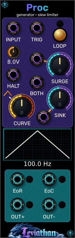
The 8 HP panel has five controls, a waveform preview, six inputs, and four outputs. Separate views below identify controls and jacks. Click a numbered marker to reach its description.
Gold button at top right
Latches continuous cycling on or off. The small light above the button shows cycle status. Proc has no separate Cycle CV input.
Upper large knob on the right
Sets rise time. The adjacent rising-slope input (10) modulates it. Stage times depend on the knob, Curve, and CV; engine limits are 0.1 ms–1500 s per stage.
Lower large knob on the right
Sets fall time. Fall CV is the jack below and to the left (12). Equal rise/fall times at the linear Curve point produce a triangle.
Large knob on the left
Reshapes both stages and changes overall timing. Linear is at 33% travel. Proc has one curve law and no Mirror/Shark Fin switch.
Small knob below INPUT
Sets the function amplitude target from 0 to 10V; default 8V. The readout shows the setting, not a measured output peak. AMP is bypassed during idle slew operation.
Wide window below the controls
Shows nominal cycle geometry and a calculated frequency estimate. The low-rate dot tracks active functions and hides above about 2.4 Hz or while idle. This is not an input oscilloscope.
Purple-ringed jacks are inputs; cyan-ringed jacks are outputs. Rising and falling slope glyphs identify the two stage CV inputs. HALT pauses the core; TRIG starts a function.
Top-left jack
Feeds the slew limiter when Cycle is off and no triggered function is active. During a function, a patched signal pulls the core voltage toward the input.
Top-center jack
Rising edge at 1V, re-arm at 0V. Triggers during rise or HALT are ignored. An accepted trigger during fall resets the core to 0V; from idle slew, rise starts at the current core voltage.
Left jack below the amplitude readout
At 2.5V or above, holds core voltage and gate states. AMP still scales a held function; existing bandlimiting tails can settle. Release resumes integration.
Rising-slope glyph, left of SURGE
Positive CV lengthens rise; negative CV shortens it. This input is separate from TRIG.
Center jack between HALT and SINK
Changes rise and fall together. Positive CV speeds up; negative CV slows down. Its saturating response is not calibrated 1V/oct.
Falling-slope glyph, below-left of SINK
Positive CV lengthens fall; negative CV shortens it.
Upper-left jack in the output block
Nominal 0/10V gate: high during fall, low during rise and idle. In slew operation, indicates downward motion. HALT preserves its state.
Upper-right jack in the output block
Nominal 0/10V gate: high during rise, low during fall and idle. In slew operation, indicates upward motion. HALT preserves its state.
Bottom-left jack
Function output scaled by AMP, or the slewed input at unity gain while idle. Slewed bipolar input can make OUT+ negative; the plus sign identifies the non-inverted output.
Bottom-right jack
The exact negative of OUT+. In idle slew operation it inverts the slewed input; it can be positive when OUT+ is negative.
CV and patching
Use the panel labels below to identify jacks. Gate levels are nominal; optional bandlimiting can introduce transient deviations.
| Port | Type | Range / Voltage | Operational Behavior |
|---|---|---|---|
| INPUT | Signal In | +/-10 V audio / CV | Slew limiter input. When Cycle is off and idle, output tracks this input limited by Surge and Sink rates. |
| TRIG | Trigger In | Rising edge at 1 V; re-arm at 0 V | Starts Rise; triggers during Rise are ignored. During Fall, an accepted trigger resets the core to 0V and rises. From idle slew, Rise starts at the current core voltage. Accepted triggers have a 0.5 ms re-arm interval. |
| HALT | Gate In | High threshold 2.5 V | Freeze gate: At 2.5V or above, suspends core integration and preserves gate states. AMP can still change the scaled function output, and existing bandlimiting tails can settle. |
| RISE CV | Modulation | +/-10 V exponential | Modulates Surge. +V increases time (slower); -V decreases time (faster). |
| FALL CV | Modulation | +/-10 V exponential | Modulates Sink. +V increases time (slower); -V decreases time (faster). |
| BOTH CV | Modulation | Bipolar, saturating speed control | Scales Surge and Sink together with a saturating response: positive CV speeds up, negative CV slows down. It does not provide calibrated 1V/oct tracking. |
| OUT+ | Signal Out | Nominal 0 to +AMP V; slew follows input | Function output scaled by AMP; while idle with INPUT patched, follows the input through the slew limiter. In slew mode, OUT+ can be bipolar. |
| OUT- | Signal Out | Nominal 0 to -AMP V; inverted slew | Inverted function generator output (-OUT+). Perfect for complementary VCA ducking or reverse sweeps. |
| EOR | Gate Out | 0 V / +10 V | End of Rise: High (+10V) during Fall; low during Rise and idle. In Slew mode, high when slewing downward. HALT preserves the gate state. |
| EOC | Gate Out | 0 V / +10 V | End of Cycle: High (+10V) during Rise; low during Fall and idle. In Slew mode, high when slewing upward. HALT preserves the gate state. |
Distinguishing characteristics
While sharing the core variable-curvature integration engine of Integral Flux, Proc introduces specialized features for standalone utility and control.
The HALT input pauses the core in any operating mode:
Instead of requiring an external attenuator or central mixer channel:
Proc eliminates the need for an external inverter:
Unlike Integral Flux where EOR belongs to CH1 and EOC belongs to CH4:
Operating modes
Proc adapts dynamically to your patch cable connections.
Engaged when LOOP is on or when pulses are sent to TRIG:
Engaged when a cable is patched into INPUT, Cycle is off, and no triggered function is active:
Curvature engine
The CURVE knob reshapes both Surge and Sink segments with mathematical phase normalization.
| Curvature Setting | Rise Response | Fall Response | Musical Applications |
|---|---|---|---|
| 0% to 32% (Logarithmic) | Rapid initial rise, rounded peak | Slow initial drop, faster finish | Rounded attacks and falls that accelerate toward zero. |
| 33% (True Linear) | Strict constant ramp rate | Strict constant ramp rate | Uncolored pitch glissandi, symmetric triangle LFOs, linear CV ramps. |
| 34% to 100% (Exponential) | Creeping start, steep explosive peak | Fast initial drop, gentler finish | Accelerating attacks and decays that slow toward zero. |
Visual inspection
Proc features a waveform preview window displaying real-time cycle geometry and timing.
The window renders the nominal cycle shape determined by Surge, Sink, and Curve:
Below the visualizer, the calculated frequency estimate (1 / (rise time + fall time)) adapts its units. It is not a measurement of external input frequency:
Context menu
Right-click Proc's panel to access deep engine configurations.
| Option | Default | Description |
|---|---|---|
| Bandlimited EOR/EOC | Disabled | Uses minBLEP anti-aliasing on EOR and EOC output edges to reduce aliasing when using the gates as audio signals; this is not a click-removal guarantee. |
| Bandlimited Signal Outputs | Enabled | Anti-aliases sharp envelope reset transitions to reduce step-related aliasing; it does not bandlimit the entire waveform. |
| Timing Update Rate | 1 (Per sample) | Allows control-rate decimation (/4, /8, /16, /32) to reduce timing-calculation cost. Interpolate Timing Updates is enabled by default and smooths changes between updates. |
| Preview Tracer | Enabled | Toggles the low-rate animated phase tracer. Experimental phosphor controls are debug-only. |
Patch recipes
Explore the sonic versatility of Proc with these creative starting configurations.
Goal: Pause the internal LFO to create held sections in a pitch modulation signal.
1. Enable LOOP with Surge and Sink at ~1 Hz (slow LFO).
2. Patch a 16th-note gate sequence into HALT.
3. Patch OUT+ into a synth voice pitch input.
Goal: Duck a VCA that supports additive bipolar level CV.
1. Turn LOOP off, leave HALT low, and patch the kick trigger into TRIG.
2. Set Surge to minimum, Sink to ~25%, and Curve clockwise from the 33% linear point for a fast initial fall and gentler finish.
3. Set AMP to 5.0 V.
4. Open the VCA with its manual level or a positive bias, then add OUT- to its bipolar level CV input. Adjust CV depth to taste.
Goal: Detect whether a complex modulation source is moving up or down.
1. Turn LOOP off, leave TRIG unpatched and HALT low, then patch an LFO or sequencer into INPUT.
2. Set Surge and Sink to ~10% (slight smoothing).
3. Monitor EOC (high while voltage is rising) and EOR (high while voltage is falling).
Goal: Pause and resume an audio-rate function with a gate.
1. Turn Surge and Sink to near-minimum (watch the frequency estimate; Curve changes the rate).
2. Enable LOOP.
3. Patch a 0/10V rhythmic gate into HALT. High pauses the function; low lets it run. For run-on-high behavior, use a gate inverter that outputs a positive gate when its input is low.
4. Listen to OUT+.
Goal: Divide an incoming master clock by /2, /3, or /4.
1. Turn LOOP off and patch a master clock into TRIG.
2. Patch EOR into your divided clock destination.
3. Keep Sink short and lengthen Surge across multiple clock periods. Tune while monitoring EOR; division ratio depends on timing.
Goal: Set a 5V function amplitude target for filter modulation.
1. Turn LOOP off, leave HALT low, and patch a gate into TRIG.
2. Turn AMP until the readout shows exactly 5.0 V.
3. Shape Surge and Sink to taste.
4. Patch OUT+ into your VCF Cutoff CV.
Troubleshooting
Check the HALT input jack. If a cable is connected and the voltage is at least 2.5V, Proc's core is intentionally held in pause mode. Disconnecting or pulling HALT low resumes normal integration immediately.
By design, the AMP knob sets the amplitude target of internally generated function envelopes (0 to +AMP V). When Cycle is off and no triggered function is active, the patched signal is slewed with unity gain. During an active triggered or cycling function, AMP still applies and the input perturbs the core.
On Integral Flux, CH1 provides EOR and CH4 provides EOC. On Proc, both EOR and EOC are available simultaneously on the single channel! Furthermore, in Slew mode, EOC signals rising voltage and EOR signals falling voltage.
Proc's Curve knob has true linear response at 33% knob travel. Values below 33% warp into logarithmic curves; values above 33% warp into exponential curves.
Technical reference